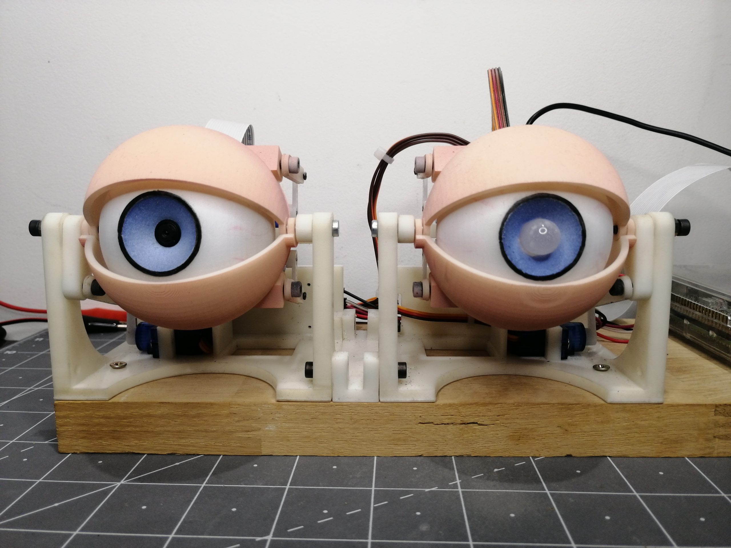
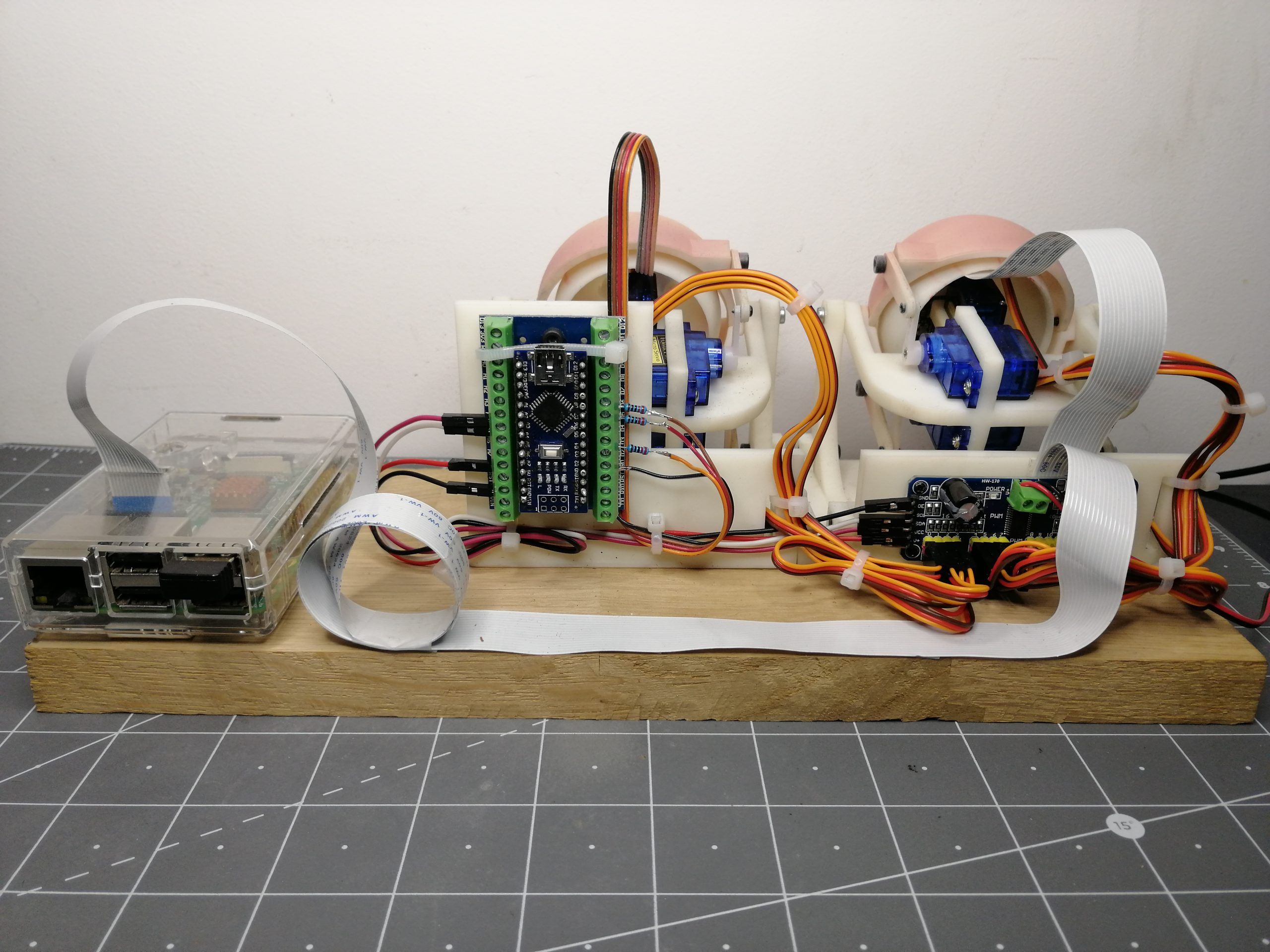
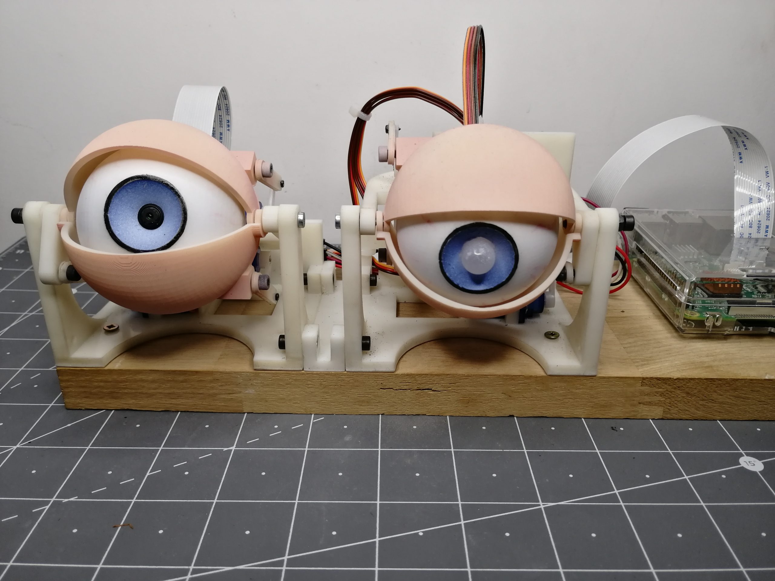
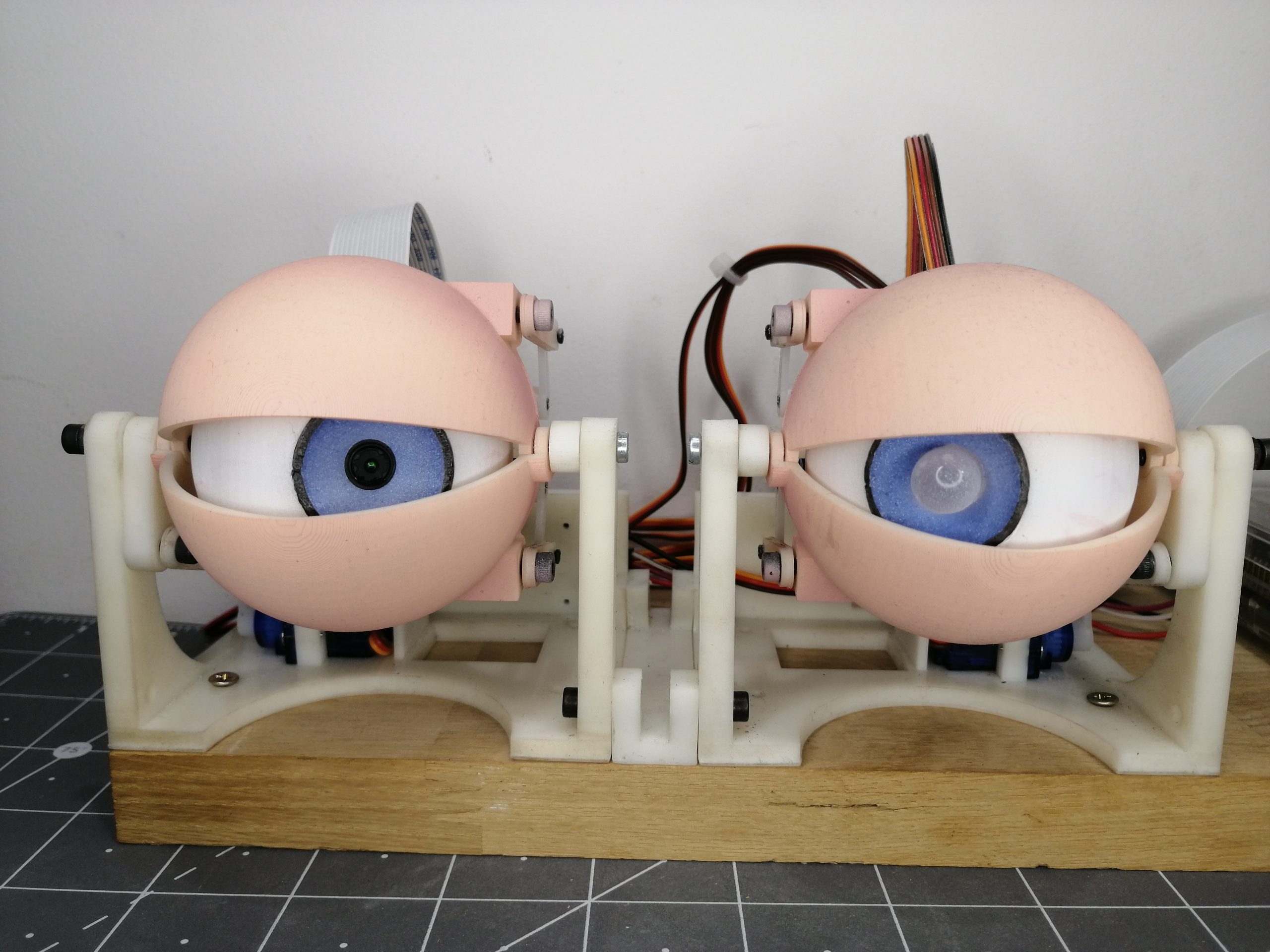
Description : Yeux animatroniques pilotés à l’aide d’une PI caméra et Open CV pour le suivi de 2 couleurs (vert et jaune).
Un microcontrôleur Arduino est chargé d’orienter les servos grâce à la réception de coordonnées envoyées grâce à un code python.
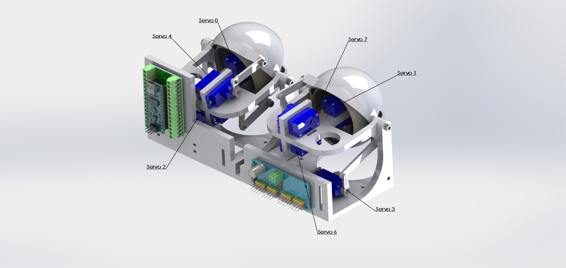
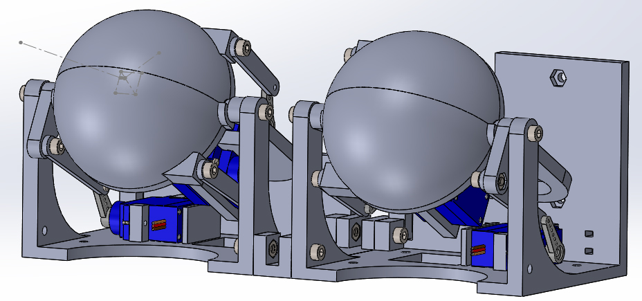
La conception des yeux avec la caméra embarquée a été faite de façon à ce que chaque assemblage dispose d’un écrou et d’une vis afin de rendre le montage fiable et fluide dans le temps. Chaque pièce a été faite pour qu’elle soit facilement imprimable sur une imprimante résine voir filament (test pas encore effectué). Tous les fichiers sont disponibles ci-dessous en téléchargement.
Vidéo de démonstration :
VIDEO
Composants nécessaires :
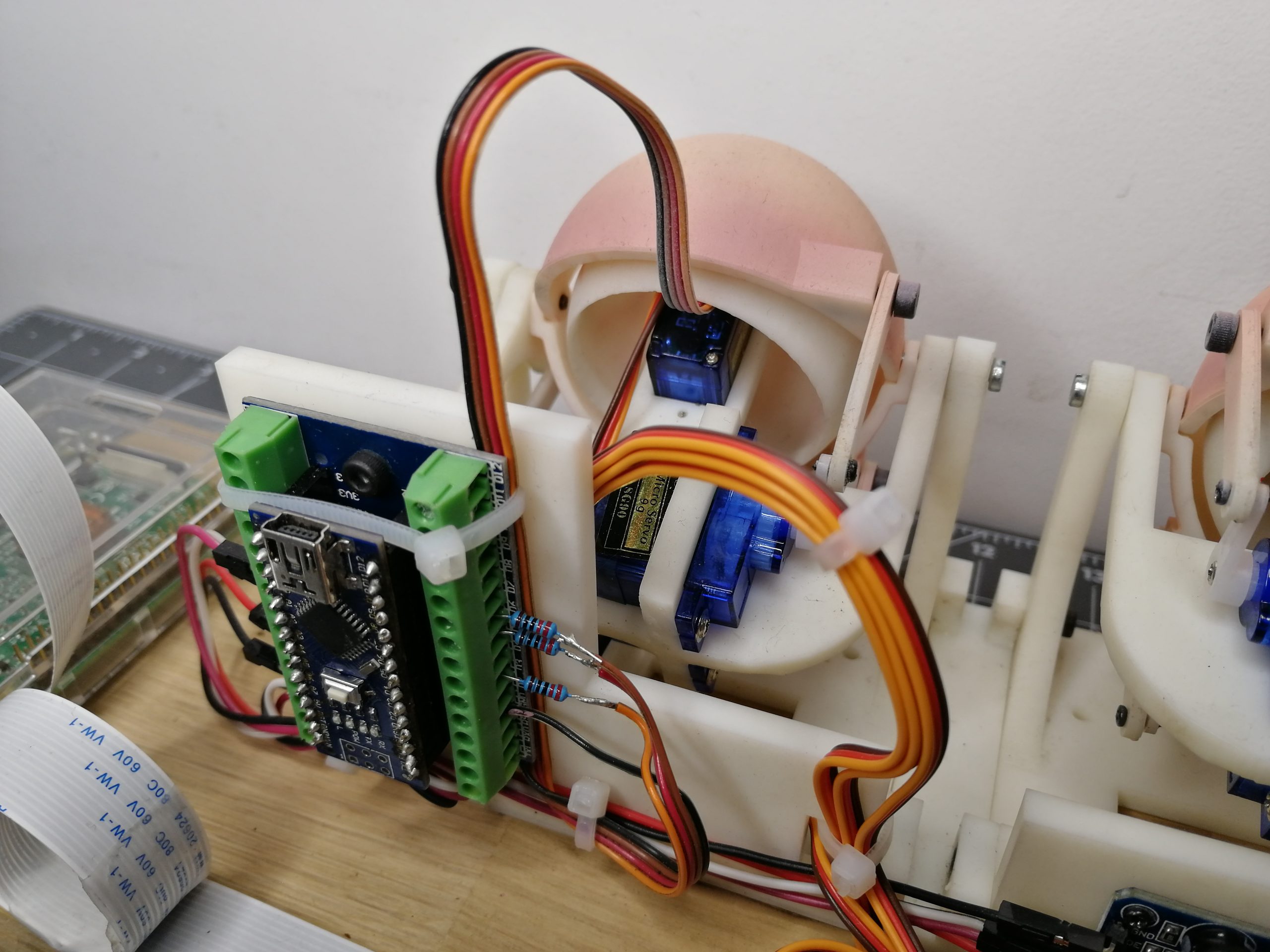
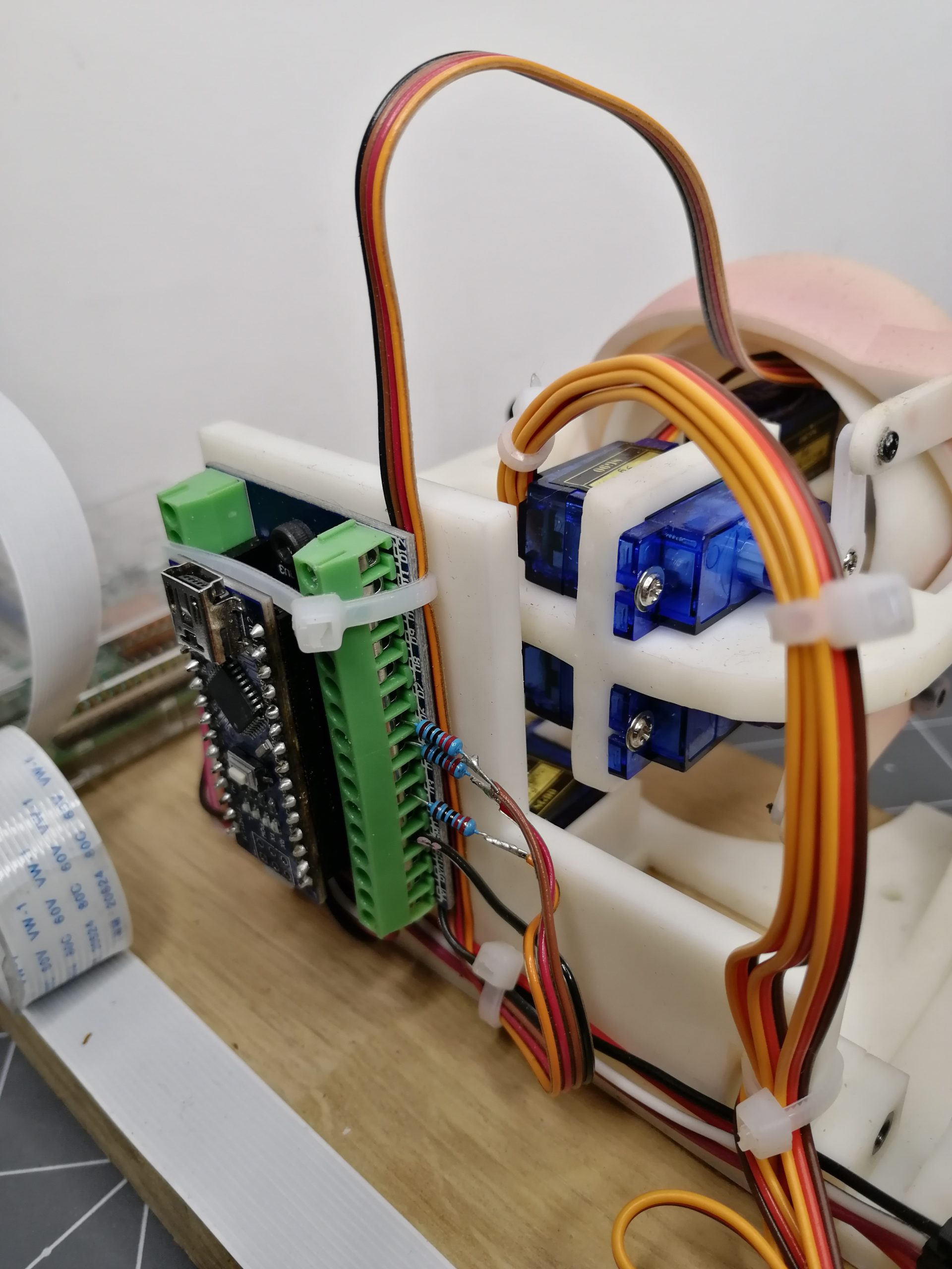
Arduino Nano
Carte d’extension pour module de contrôle Nano
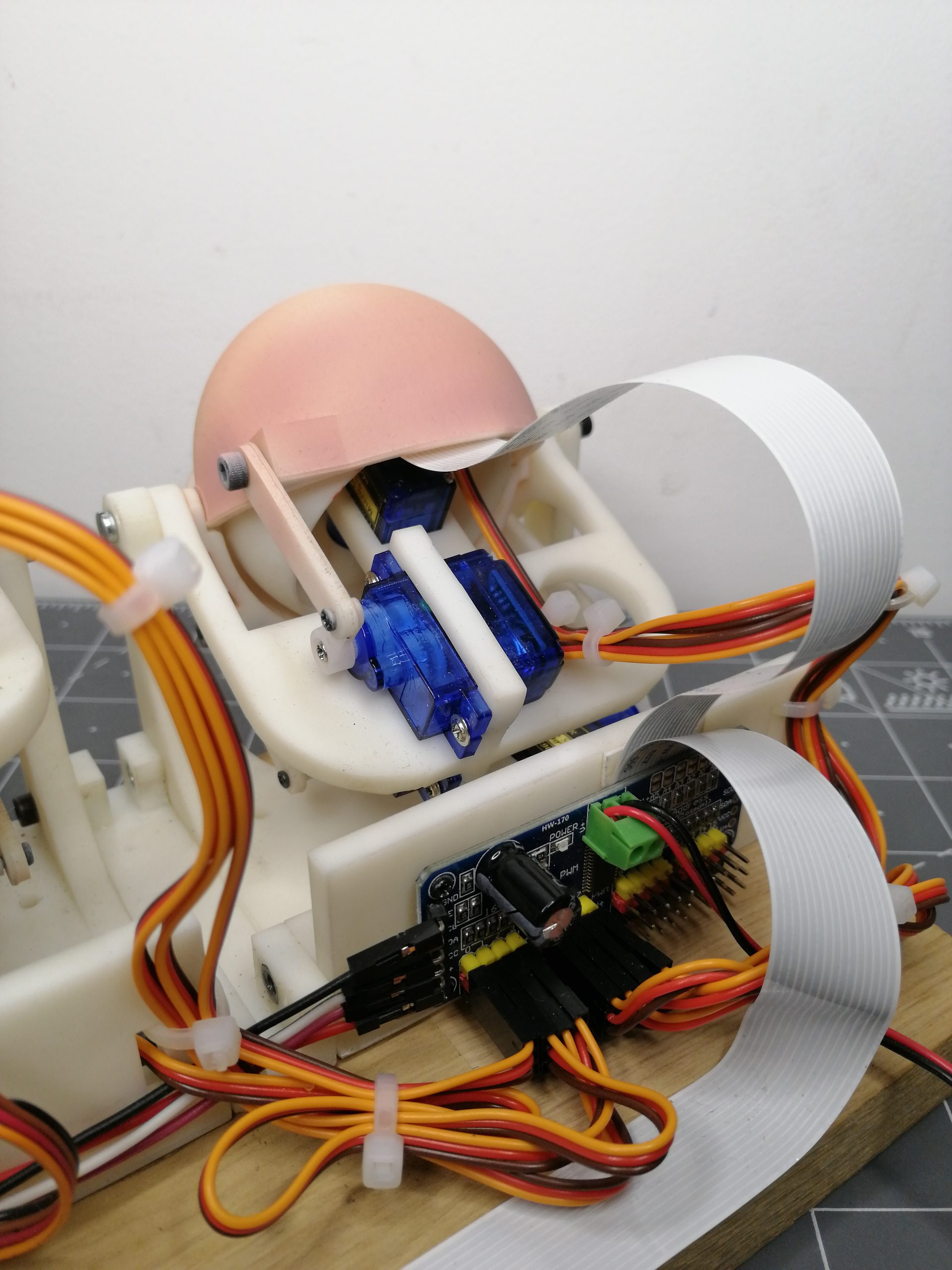
1 PCA9685
Des fils de connexion
1 alimentation 5v
4 vis M3x16
8 vis M3x8
4 vis M3x10
16 écrous hexagonal M3
14 Vis tête ronde auto taraudeuse M1.7X6
1 imprimante 3d résine ( imprimante filament test pas encore effectué)
1 Raspberry PI 3
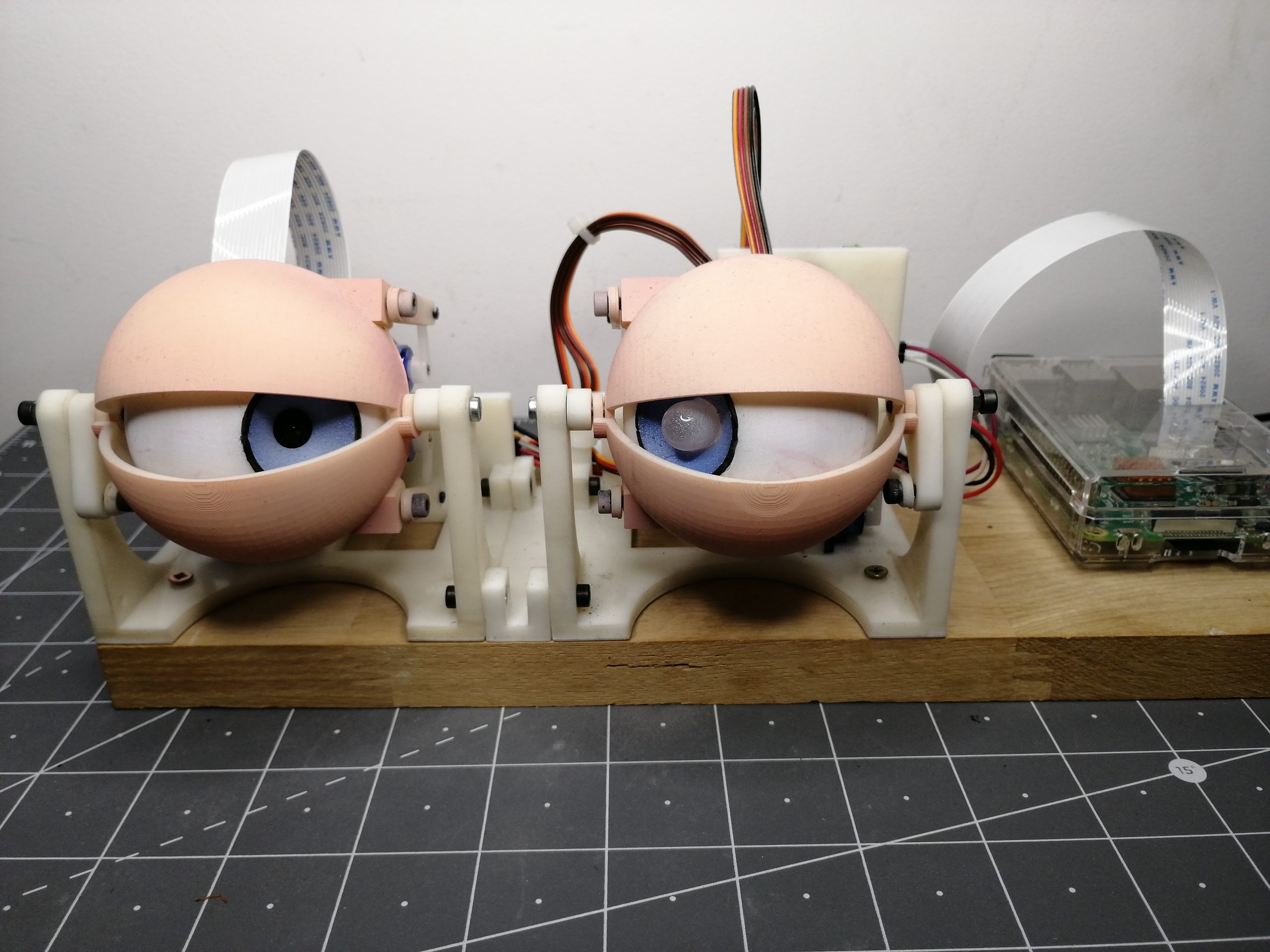
1 Camera PI v2.1
1 LED RGB
3 résistances 220Ω
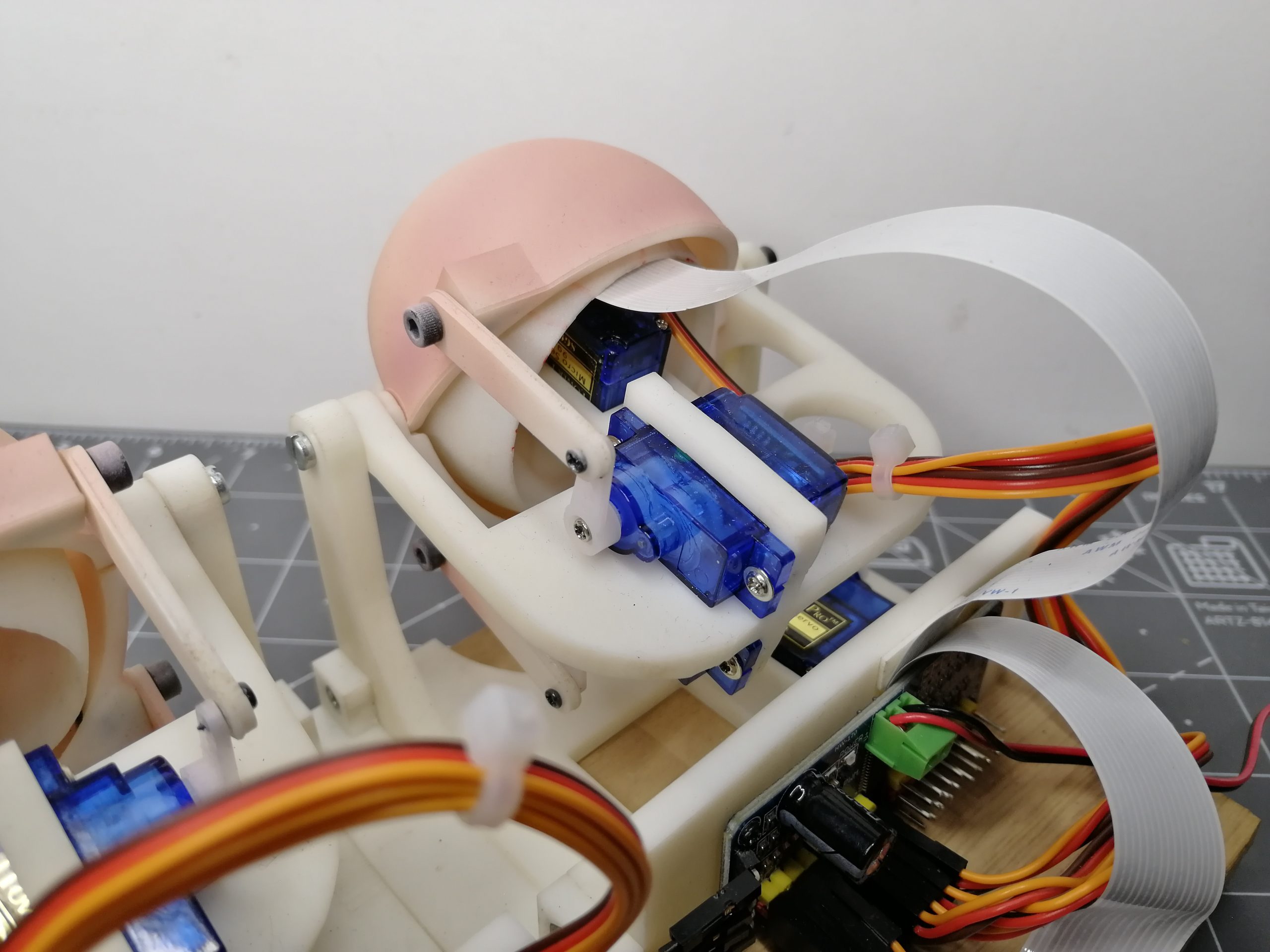
8 Servos Tower pro 9g sg90 (attention à la sortie des fils voir ci-dessous)
Fichiers SolidWorks et STL :
Bibliothèque nécessaire :
#include « Adafruit_PWMServoDriver.h »
https://github.com/adafruit/Adafruit-PWM-Servo-Driver-Library
Logiciels nécessaires pour le Raspberry :
Python 2.7
OpenCV
pyserial
NumPy
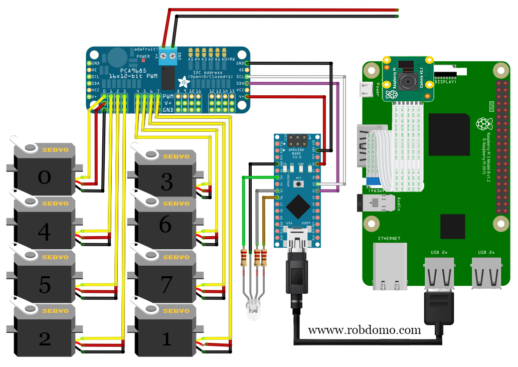
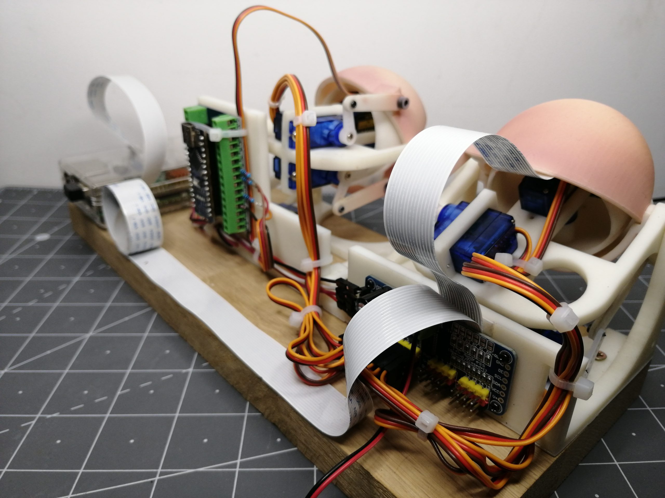
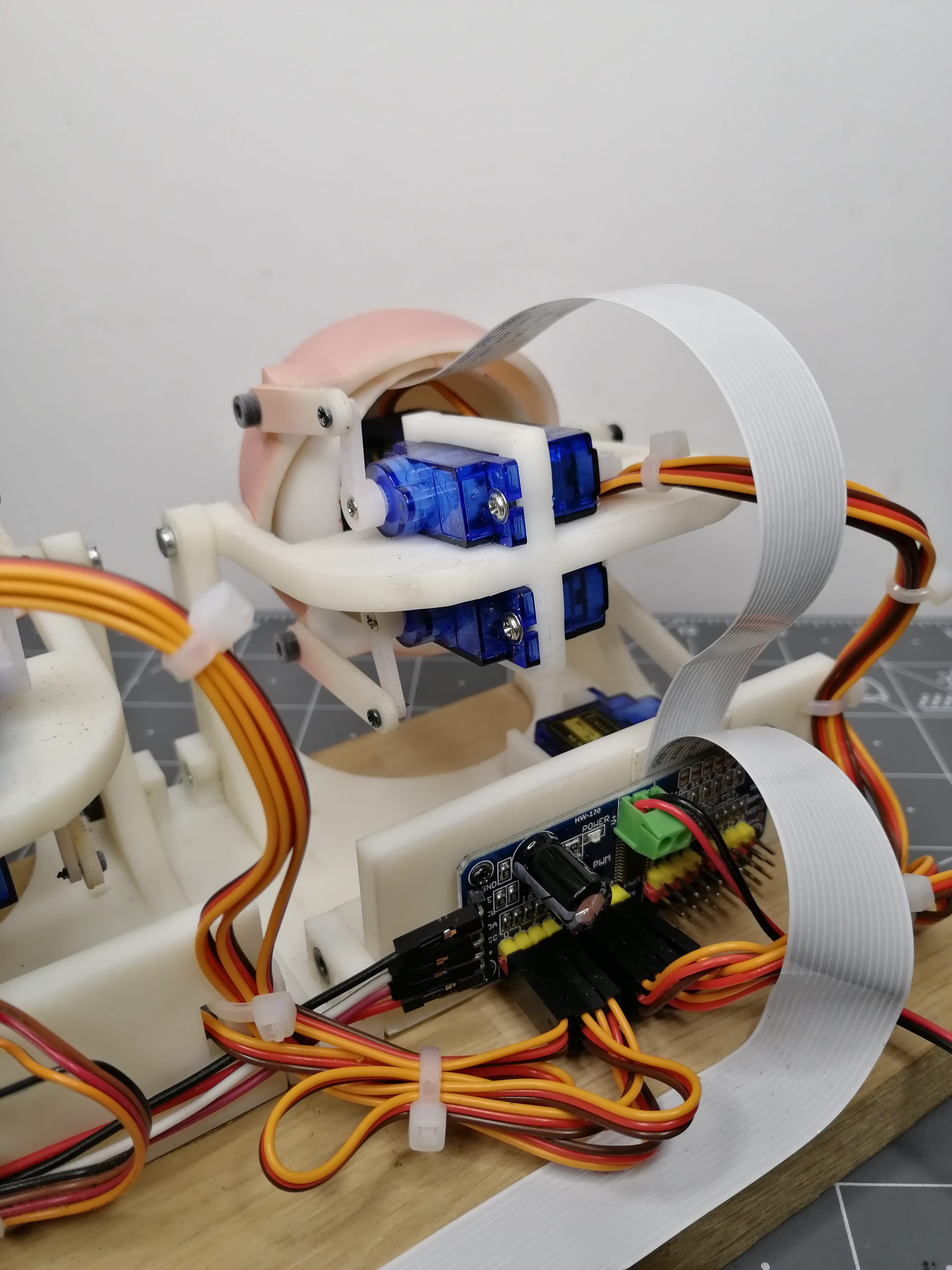
Schéma de câblage :
Attention aux câblages des servos et à leur nom.
Par exemple le servo 2 est branché sur la sortie 3 du PCA9685.
Résumé :
Servo 0 –> Pin 0
Servo 1 –> Pin 7
Servo 2 –> Pin 3
Servo 3 –> Pin 4
Servo 4 –> Pin 1
Servo 5 –> Pin 2
Servo 6 –> Pin 5
Servo 7 –> Pin 6
Codes pour positionner les servos avant assemblage final :
#include "Wire.h"
Vous devez obtenir cette position une fois l’assemblage fini.
Codes Arduino pour le suivi de couleur :
int pinservo[]={ 0, 7, 3, 4, 1, 2, 5, 6};
Codes Python pour le suivi de couleur :
import cv2
Photos :
Nombre de vues: 796
J’aime ça : J’aime chargement…


Je souhaiterais réaliser votre projet avec arduino , et avec une impression 3d filament PLA.
Programme arduino pas de problème.
Par contre est il possible d’avoir les dimensions des différentes pièces.
En vous remercient
Lucien Verdier
Bonjour,
Les fichiers STL et solidworks sont disponibles en téléchargement dans l’article.
Cordialement,